
SEE WHAT HAPPENS INSIDE CONCRETE
Drilling: intersecting the crack.
See where the hole reaches and where the resin flows.
First a few trial points. Then the whole section.
01 / DRILLING AND INJECTION ERRORS
Why does the resin fail to reach the right place?
The diagram shows a possible mechanism, not the outcome of every injection. Confirm the crack path and communication on a trial section.
02 / CORRECT DRILLING · ALTERNATING LAYOUT
Start with a target at 50% of the thickness.
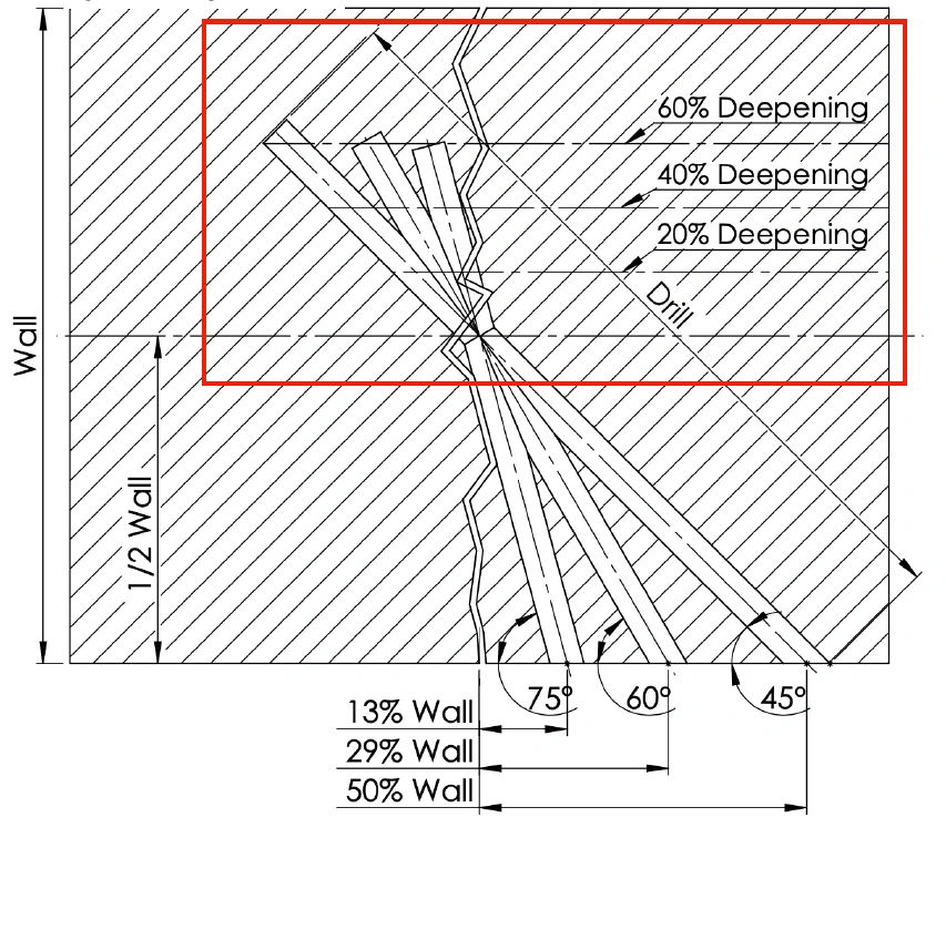
In this example, we target the middle of the cross-section, beyond the packer sleeve. Change the target to 40% or 30% and see the geometry change.
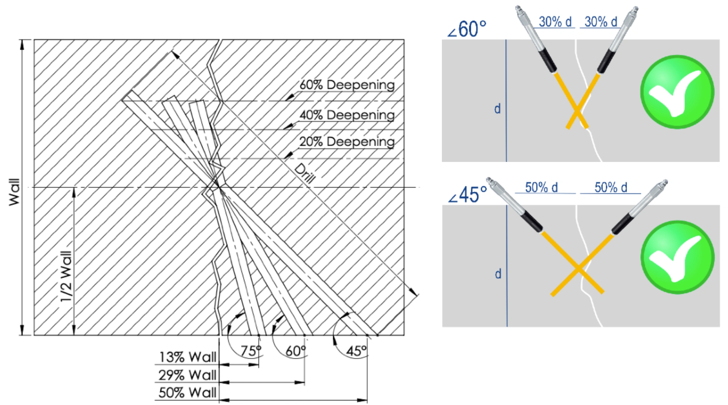
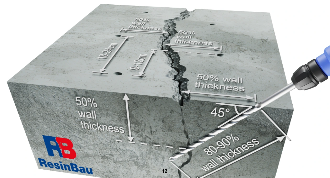
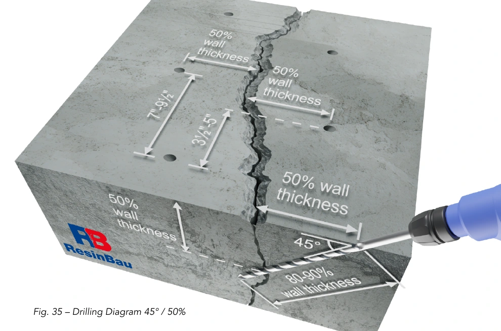
Drawings from Resinbau instructions and catalogue. Source dimensions are geometry examples; confirm spacing with a communication trial.
Spacing: next packer versus the same side
All points alternate. Distances are measured along the crack, not diagonally between heads.
No communication to the next packer? Check for blockages and crack intersection. If the system is clear, reduce spacing and repeat the trial. A narrower crack and higher material viscosity may limit flow reach.
12.5 cm is an example, not a guarantee of communication. The calculator shows geometry; it does not predict resin flow.
03 / THE CRACK IN THREE DIMENSIONS
A long crack need not be deep everywhere.
A crack may pass through the entire element in one place and end at a shallower depth elsewhere. For example, the trace is 4 m long, but only part crosses the full thickness. Water may run through the connected crack to a deeper section. Alternating boreholes may also miss the shallow part.
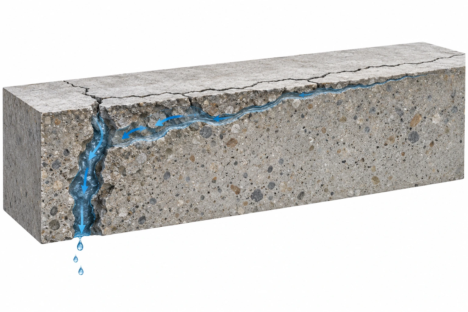
A missed borehole does not describe the whole crack.
Keep the alternating layout. Adjust the target depth and verify intersection in a trial.
Conceptual diagram. Alternation does not replace assessment and a communication trial. Spacing, depth and access from both sides depend on element conditions.
View original Resinbau drawings
04 / FROM ASSESSMENT TO INSPECTION
First a trial. Then a repeatable process.
Switch stages and observe holes, packers and the material path.
Sequence diagram for crack injection. Select cleaning, face sealing, pressure and top-up injection time for the material, substrate and trial result.
05 / INTERPRET THE SIGNAL
Not every discharge means the same thing.
06 / APPLY IT ON SITE
First a few trial points.
- Check the cross-section. Thickness, crack path and access.
- Select the borehole and packer together. Intersection beyond the sleeve, with outlet access to the crack.
- Clean the hole. Observe flow. A pressure rise alone does not confirm intersection.
FROM DIAGRAM TO DIMENSIONS
Calculate angle and offset.
45° is one option. Angle, offset and hole length together determine the intersection location.
Open the drilling calculator ↗Technical basis and details
Prepared from “Cracking the Injection Code”, PDF pp. 45–50, and the author's “Injection Process Control” training: assessment and preparation, geometry checks, observation and controlled closure of the system. The drawings concern expansion packers; they do not describe bonded surface ports.
A crack in an actual element may change direction. Lack of flow may also result from dust, a blocked valve or material properties. Communication to the next packer confirms a connection but does not alone prove complete filling of the cross-section. Compression here means controlled retention of material in the system, not maximum pressure. Remove packers after suitable material curing according to the system instructions. Select face sealing for the system, retaining planned observation and venting points.